Per Unit System Problems With Solutions
There is a lot of confusion surrounding the per unit system, and rightfully so. If you've never used it before, it is easy to become confused with all of the individual pieces that make the system work.
To help clear things up, here is an in-depth break down on an example question that is similar to what you can expect to see on the NCEES Electrical Power PE Exam.
Related Per Unit Articles:
Electrical PE Review – Base Changing Percent Impedance and Per Unit Impedance
Electrical PE Review – Calculating Base Impedance with Three Phase vs Single Phase Values
What's in this article? – Per Unit Example – How To, Tips, Tricks, and What to Watch Out for on the Electrical PE Exam:
Click below to jump to any section.
- Per Unit PE Exam Practice Problem
- Step 1: Separate by Voltage Zones
- Step 2: Assign Base Values
- Step 3: Calculate Base Impedance for Each Zone
- Step 4: Calculate the Per Unit Impedance for Each Zone
- Step 5: Calculate the Per Unit Impedance for Transformer T1
- Step 6: Calculate the Per Unit Impedance for Transformer T2
- Step 7: Calculate the Per Unit Current and Per Unit Voltage
- Step 8: Use Ohm's Law to Calculate the Per Unit Current
- Step 9: Calculate the Base Current in Each Zone
- Step 10: Calculate the Actual Current in Each Zone
- Step 11: Check Your Work Using the Transformer Ratios
- Step 12: The Completed Diagram
1. Per Unit PE Exam Practice Problem
Using the Per Unit system and taking into account the transformer percent impedances, solve for the current in each part of the three-phase system shown below. Assume both transformers are either delta – delta or wye – wye connected and that there is no phase shift between primary and secondary current and voltage.
![]()
(Go back to top)
Step 1: Separate by Voltage Zones
The usefulness of the per unit system is in converting all system impedances to per unit impedances and re-drawing the circuit without having to worry about the different voltage levels from each transformer.
In this example, there are two transformers that divide the system into three different voltage zones that are created by the stepping up or stepping down of voltage by each transformer.
The first step is to illustrate this by drawing a straight line through each transformer:
![]()
(Go back to top)
Step 2: Assign Base Values
The next step is to choose the base values for power and voltage.
The base power will be the same in for each zone, but each zone will have a different base voltage.
The problem might tell you to use specific values for base power and voltage. If it does, use them accordingly as the answer choices will most likely still be in per units and using a different base will change the resulting per unit system values.
If the problem does not assign the base values for you, then it is advantageous to pick one of the existing MVA values in the system such as the apparent power rating of one of the machines.
Similar for voltage, it is advantageous to pick one transformer and use either the primary or secondary voltage as the base voltage in a particular zone, and then use the remaining transformer ratios to step up or down the voltage base for each neighboring zone accordingly. Why this is advantageous will become clear when we run the math.
If all transformer ratio's match, then the secondary voltages of all upstream transformers are equal to the primary voltage all downstream transformers and vice versa, then your voltage base in each zone will be equal to the primary and secondary voltages of each transformer. That is the case for this example.
For base power, I've arbitrarily picked T1's MVA rating for the system and the voltage ratios of the transformers for the base voltage in each zone:
![]()
(Go back to top)
Step 3: Calculate Base Impedance for Each Zone
Now that we have the assigned base values for power and voltage, we'll need to calculate the base impedance for each zone so that we can use it to calculate the per unit impedances later on.
The formula for base impedance is:

We can solve for impedance using voltage and power, and if we use the base voltage and base power in each zone, then the resulting impedance will be the base impedance for each zone as shown below:
![]()
(Go back to top)
Step 4: Calculate the Per Unit Impedance for Each Zone
Now that we have calculated the base impedance for each zone, we can start calculating the per unit impedances of each system element using the following formula:

We will start by calculating the per unit line impedance and per unit load impedance first before we tackle the transformers.
The line per unit impedance and load per unit impedance are calculated as shown below:
![]()
Now that we know the per unit line and load impedances, let's draw them on the per unit circuit diagram:
![]()
(Go back to top)
Step 5: Calculate the Per Unit Impedance for Transformer T1
In order to complete the above diagram, we'll need to calculate the per unit impedances of both transformers T1 and T2.
The catch here is that we don't know either of the transformer impedances in ohms, we are instead given their percent impedances.
When you are given the percent impedance of a machine such as a transformer, generator, or motor, the percent impedance is given in the base ratings of the machine itself.
This means that in order to calculate the percent impedances of the transformers, we actually need to perform a per unit base change using the following formula:

In this case, the old base will be the ratings of each transformer, and the new base will be the new bases we have chosen.
Since we are working with impedances, we will need to plug in the impedance formula that uses the square of the voltage divided by power:

In the above formula, S BASE NEW and V BASE NEW will be the chosen bases of our system and zone, and S BASE OLD and V BASE OLD will be the transformer voltage and power rating.
Transformers have one power rating, so choosing that is easy. However, they have two voltages, a primary and secondary.
If we use the transformer's primary voltage for V we will need to use the base voltage on the primary side of the transformer for VB in the formula above.
If we use the transformer's secondary voltage for V then we will need to use the base voltage on the secondary side of the transformer for VB instead.
This will be more clear when we work out the math below.
Let's base change each transformer's percent impedance one at a time starting with transformer T1 using the primary voltage rating as V and the voltage base on the primary side of the transformer for VB:
![]()
(Go back to top)
Step 6: Calculate the Per Unit Impedance for Transformer T2
Notice that since we originally chose 45MVA as the base power for the system, both power terms are equal and cancel. This will not be true for T2.
Also, notice, that both voltage values are also equal and cancel since the base voltage in each zone is equal to each transformer's voltage ratio.
It is important to be aware that the voltage values in the above formula will not cancel when the actual voltage in a zone is not equal to the transformer's voltage ratios such as when a generator is connected that supplies a voltage slightly higher or slightly lower than the primary voltage ratio of the transformer it is connected to, or, when all transformer ratios do not match as mentioned in the first several paragraphs.
Notice that since our base power and base voltage for T1 equal the base values we were changing to, there is no actual change in the percent impedance. We started with 5% and ended with 5%.
Last bit of importance is to notice the imaginary "j" term placed in front of the final per unit impedance value for T1.
Transformers are made up of large inductive coils and their impedance is mostly reactive.
The PE exam may not remind you of this and it will be up to you to not only recognize that this is actually a reactive impedance but to also add the imaginary j term to it.
Let's move on and calculate the per unit impedance for transformer T2:
![]()
(Go back to top)
Step 7: Calculate the Per Unit Current and Per Unit Voltage
Now that we have both per unit impedances let's fill in the remaining values in our per unit impedance diagram.
Again, notice that both transformer per unit impedances are reactive terms and we had to add the "j" multiplier:
![]()
Now that we have all impedances converted to per unit values of the same base, it's time to calculate the per unit current using Ohm's law:
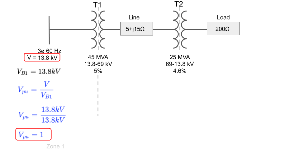
However, in order to calculate the per unit current, we will need to calculate the per unit voltage.
Luckily for us, the voltage on our input bus is equal to the base voltage selected in that zone which simplifies the math since both terms cancel:
(Go back to top)
Step 8: Use Ohm's Law to Calculate the Per Unit Current
Since the input voltage is equal to the base voltage in zone 1, the per unit voltage at the source of our per unit impedance diagram is equal to 1.
This greatly simplifies solving for the per unit current which will now equal the inverse of the total series per unit impedance of the system:
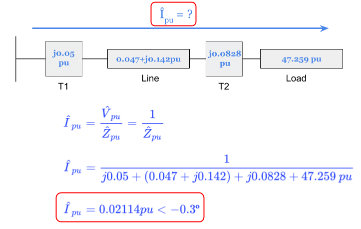
The per unit current will be the same value for each voltage zone.
(Go back to top)
Step 9: Calculate the Base Current in Each Zone
Now that we know the per unit current, we can finally calculate the actual current in each voltage zone by multiplying by the per unit current by each base current:
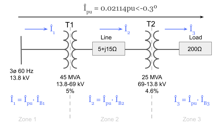
However, this requires us to know what the base current in each voltage zone is equal to.
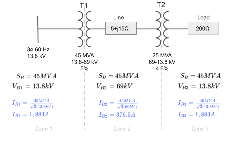
We can calculate it using the chosen base power and the chosen base voltage in each zone as shown below.
Notice the √3 multiplier since it is a three phase system:
(Go back to top)
Step 10: Calculate the Actual Current in Each Zone
Now that we have each of the base current values we can complete the problem and solve for the actual current in each zone in amps:
![]()
We can now fill in the current in amps for each zone to the original system diagram that we started with:
![]()
(Go back to top)
Step 11: Check Your Work Using the Transformer Ratios
For a quick check of our work, we can use the transformer voltage ratios to verify our currents are equal in each zone depending on voltage level.
If we did our work correctly we should get almost the exact same answer for each current by starting with one and using the transformer ratios to solve for the rest
Let's start with current I3 and work our way back to I2 and I1:
![]()
Looks good! Everything checks out.
(Go back to top)
Step 12: The Completed Diagram
Here is our final answer solving for the individual currents in amps of the original system using the per unit method:
![]()
Hope you enjoyed this exercise using the per unit system.
(Go back to top)
Related Per Unit Articles:
Electrical PE Review – Base Changing Percent Impedance and Per Unit Impedance
Electrical PE Review – Calculating Base Impedance with Three Phase vs Single Phase Values
Per Unit System Problems With Solutions
Source: https://www.electricalpereview.com/per-unit-example-tips-tricks-watch-electrical-pe-exam/